
Cache Coloring
I was reading a paper [1] that describes how to patch side-channel leakage by providing an abstraction at the
OS level. It was a good read, although I was unable to follow most of the
details on the microkernel designs that are specific to the L4 kernel. But one
sentence stood out and kept bugging me for two days:
On most hardware the OS cannot colour the small L1, .., because they are generally indexed by virtual address, which is not under OS control.
A bit of context here is necessary. The paper was at that point describing how partitioning the cache (one for each security domain) can be done via page colouring (I vaguely recalled that page colouring is about giving different colour to adjacent pages). But then when it said that colouring cannot be done for L1 caches for they are virtually indexed, the gap in my knowledge about caches becomes wider and I couldn’t understand the conclusion. Being obsessive with details is sometimes good, since it forced me into spending another day going back to the basic, with the ultimate end goal of verifying that the above sentence is true.
Cache here, cache there, cache everywhere
Cache is an important piece of the memory hierarchy. Whenever there is a big gap between performance of two storage layers, a cache can come in to improve performance significantly. In fact, cache is everywhere. Any storage layer can act as a cache, sitting between one faster but more expensive layer, and one slower but cheaper layer.
- L1 is a cache for L2
- L2 is a cache for L3.
- L3 is a cache for DRAM.
- DRAM is a cache for disk.
- Disk is a cache for remote disk.
The job of the cache is to kept the data as close to the CPU as possible. The closer it is, the lower the access latency. For example, L1 cache brings data from RAM to the cache, which is on-die and can be accessed very quickly by the CPU (only slower than registers themselves). As another example, DRAM brings data from disk and keeps it closer to the CPU for the applications. Without DRAM cache, CPU can read the data directly from disk and store in registers, but who would want that (or, who could do that)? Another example of caching is Redis or Memcached, that are caches for web application contents. They bring static content closers to the users (who fetch the content using web browsers).
Cache works well in practice thanks to the locality properties in most application. In particular, applications tend to use the same sets of data many times (temporal locality), and related sets of data many times (spatial locality). Thus, by keeping popular data (or the working sets) in the cache, and pre-fetching data that is to be access soon, caches can give performance a significant boost. This is important in data management applications where accessing data one big bottleneck, as opposed to analytics applications like ML in which computation is the bottleneck.
Cache management is explicit in many applications. For instance, in databases, the buffer pool component that brings data into memory from disk is one of the most complex and important component. Similarly, the OS caches pages from disk in the page cache in order to speed up read and write access to files. These cache sub-systems are implemented in software and involve complex policies for pre-fetching, replacement, and consistency. In the following, I will focus more on hardware caches, that are transparent to the applications, i.e. the applications (even the OS kernel) do not have full control over how the caches operate.
CPU caches
Recall that CPU caches provide service to the CPU. In fact, the caches are part of the Memory Management Unit (MMU), a black box on the die, as far as the CPU is concerned. The CPU asks the MMU to read and write to a certain virtual address, and the latter does it magic with caches and memory to perform the request. Once the MMU returns, the CPU is happy to execute the next instruction.
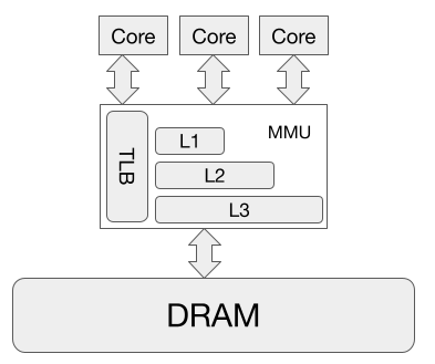
The figure above shows that this black box is a little involved. Given a request for a virtual address (VA), the MMU has to ultimately access the content at the corresponding physically address (PA) that maps to that VA. Note here that memory addresses in all CPU instructions, once the CPU enters protected mode, are all virtual addresses (the kernel runs in protected mode).
There are two simple ways to design a cache. One design is to have the MMU translates VA to PA first, then have a cache store the content of physical addresses in some form of a hash table. After address translation, the MMU lookup the PA in the hash table, and if it is there, the content is returned. This design is both easy to implement in hardware, and also easy to understand. However, it is slow (in terms of CPU cycle) because every memory address goes through translation. Granted that having a good Translation Look-aside Buffer (TLB) helps speed up translation, it is still slow (we are talking about dozen to hundred of CPU cycles here, not even milliseconds), especially for L1 cache which is the closest to the CPU.
Another simple design is to organize cache content based on virtual addresses, as opposed to physical address. This way, when the MMU receives a request for VA, it will look up in the hash table directly and return the content if exists. This design is faster than the one above, because it does not require address translation. Sounds good, right? Not really. There are two problems with this design:
-
[P1] One VAs can map to two different PA: this happens when there are multiple processes, each process use the same address (like
0x40000) but the OS maps them to two different PAs because of isolation. Using the above design means one process can read and write data of another process, thus breaking security. To solve this problem, the entire cache must be flused when switching context, incurring significant overhead. -
[P2] Two VAs can map to the same PA: this happen when multiple processes have access to share memory. For example
libcis loaded to the address spaces of different processes, and its location is random when ASLR is on. With the design above, the PA is mapped to two different entries in the cached, and keeping these entries consistent is complex and incurs significant overhead.
In summary, this design of organizing cache content based on virtual address is fast in the normal case of one single process, but becomes very complex when there are multiple processes contending the same cache.
Structure of a cache
A cache basically stores data, and its typically structure is a multi-set associative array, which looks like the figure below.
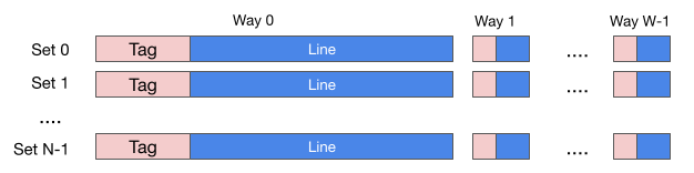
A cache is organized as N sets, each set as W ways, each way in a set consists of a line and a tag. Cache line is the unit of data stored in the cache (another term for it is cache entry, or cache block). The size of a cache, which can be found in a CPU specification, is the sum of all the cache lines, that is, the size excludes that of all the tags and other extra bits in each cache entry.
As an example, the specification of a Skylake CPU contains the following
L1 instruction cache = 32 KB, 64 B/line, 8-WAY.
L2 cache = 256 KB, 64 B/line, 4-WAY.
L3 cache = 8 MB, 64 B/line, 16-WAY.
These number means that each cache line stores 64 bytes of data, and L1 instruction cache contains 32K/(64 * 8) = 64 sets, each set has 8 ways. For L2, there are 256K/(64 * 4) = 1024 sets, each set has 4 ways. For L3, there are 8MB/(64 * 16) = 8192 sets. Another way to look at them is that L1 stores data in 8 ways, each way is 4K; L2 stores data in 4 ways, each way is 64KB; L3 stores data in 16 ways, each way is 512KB.
Different types of caches
Now that we understand the layout of a cache, the next question becomes which cache entry stores which data? Recall that CPU gives MMU a VA, and MMU must somehow look in its cache for the data in the corresponding PA. It means the MMU must know where to look for that data if it is in the cache, and where to load the data in if it is not in the cache.
How does the MMU figure out which cache entry to look up given an address. Note here that an address can be either a virtual address (one that is issued by the CPU), or a physical address (by running the virtual address through address translation which is possible because MMU has the TLB).
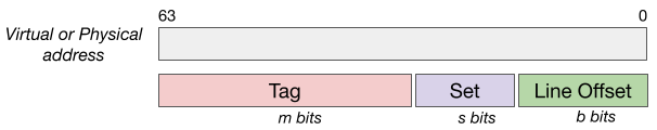
Given an address, the MMU will divide the 64 bits into 3 parts as shown in the figure above.
-
m bits are used for comparing with the tag.
-
s bits are used for the index.
-
b bits are used for the offset in the cache line.
It can be seen that m+s+b = 64, and that b is the size of the cache line, i.e., b=6. The values of s depends on the number of sets. In the example above with Skylake CPU, s is 6, 10, 13 for L1, L2, L3 respectively.
Looking up a cache entry. Given an address, the MMU uses the index bits to locate the set, then compare the tag bits with the the tag entries in the set. If there is a match, it fetches the corresponding offset in the cache line.
What type of address, i.e. VA or PA, is used to determines the tags, set, and offset bits determines the types of caches. There are four types.
Virtually Indexed, Virtually Tagged (VIVT)
As the name suggests, both the index and tag bits come from the virtual address. This is one of the design mentioned above. Recall that it is fast has two problems: multiples VAs maps to the same PA, and one VA maps to multiple PAs. It turns out that the complexity needed to address these problem outweighs the speed, thus this type of cache is not very popular.
Virtually Index, Physically Tagged (VIPT)
The index bits come from the virtual address, but the tag comes from the physical address. L1 caches implement this with m=52 (figure below).
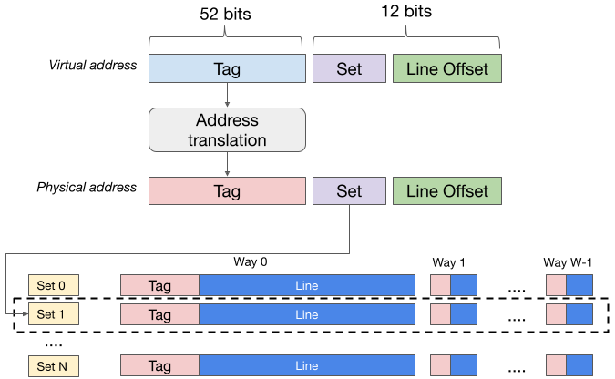
It is slower than VIVT, because there translation is need to
get the PA. Well, it solves mitigates both problems with VIVT:
-
One VA maps to two PAs: this won’t happen because different PAs will have different physical page number and therefore different tag (because m=52). As the results, the data from two different PAs will end up on different cache lines. For this to work, though, the OS must flush the TLB when context switch, or else the translation will end up with the same PA.
-
Two VAs maps to the same PA: since two VAs will have the same index bits, the content will end up in the same set. In addition, since the VAs map to the same PA, the tags will be the same. As the result, there is only one place for the data, and thus no problem with consistency.
Although it is slower than VIVT (in the absence of the problems above), the MMU can hide the latency by getting the tag in parallel with the TLB lookup. So when the translation finishes, the tags are ready to be compared.
Physically Indexed, Virtually Tagged (PIVT)
Since the tag bits are from the virtual address, this type of cache runs into the same problem as VIVT. One difference here is s+b > 12, because the index bits must be part of the physical address.
Physically Index, Physicaly Tagged (PIPT)
This is the same as the first design of the cache we mentioned above. The two problems with VIVT do not apply here, because everything is based on physical addresses. But recall the limitation of this cache is its latency, because the address need to be translated first. L2 and L3 are PIPT, as they can afford longer latency than L1, and they are simpler to design and implement.
Coloring
All these details, let’s try to understand the ideas behind page coloring. Some places, like the paper [1] and ARM documentation, refer to it as cache coloring. This multiple definitions stem from the fact that coloring is a software mechanism that is tightly coupled with hardware, i.e. cache, features.
Basic idea
Let’s consider a PIPT cache (L2 or L3, for example), where s+b > 12. In such
a cache, each way (aggregated from all the sets) has more than 4K of data.
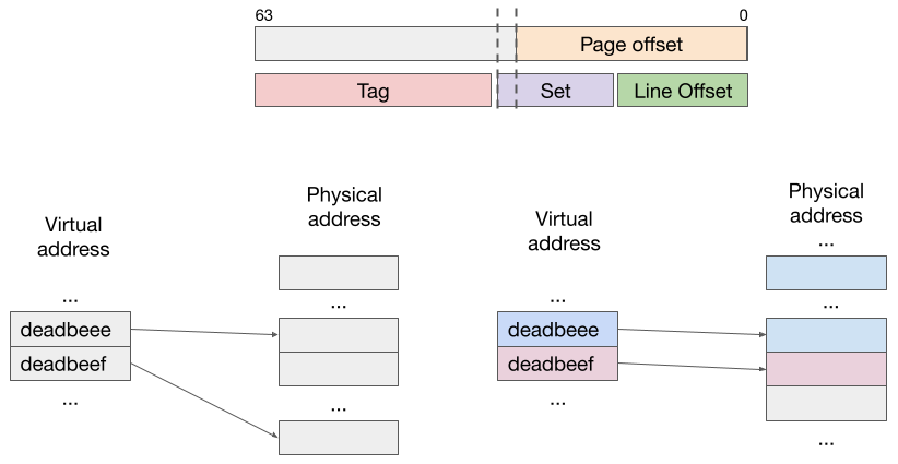
Suppose an application brings two consecutive pages into the cache. These pages
have virtual addresses of 0xdeadbeee and 0xdeadbeef. Suppose the OS randoml
maps the pages to two physical pages whose page numbers have the same last few
least significant bits. In this scenario, data at the two addresses
0xdeadbeeeXYZ and 0xdeadbeefXYZ will be in the same cache set. That is,
they will be in contention for the same cache set and may end up evicting each
other out of the set. The consequence is that the application will see more
cache misses.
There is nothing we can do about this for VIPT L1 cache, because the set
bits of 0x...XYZ and 0x...XYZ will be the same. But can we do better with
L2 and L3 cache? Yes, we can, by coloring the page.
The OS uses some bits in the physical address, e.g. s+b-12 bits, to encode
color of the page. For example, using 2 bits, there are 4 possible colors. When
the application asks to allocate several consecutive pages (very likely, as
applications do not just ask for random addresses), the OS make sure to map
them to as many different color as possible. For instance, 0xdeadbeee and
0xdeadbeef are mapped to green and red pages, respectively. Any green page,
and any red page will do. This technique reduces contention, because addresses
like 0xdeadbeeeXYZ and 0xdeadbeefXYZ will be in different cache sets,
therefore they will not content with each other. Of course, addresses from
different applications will still conflict.
The fundamental benefit of coloring is that it reduce in-application conflict on the cache. At this point, it is possible to understand why coloring is not possible for L1 that uses VIPT, because the index bits are part of the page offset. In other words, as far as L1 is concerned, all pages have the same color. If I understand correctly, though, ARM CPU has s+b > 12 for L1, meaning that it is PIPT and is amenable to coloring.
Two main uses of coloring
Coloring is useful in two scenarios.
-
Applications that need high performance. Coloring helps reduce in-application cache contention. Linux, however, does not support it. A discussion in Linux mailing list about this decision provides an interesting insight. Basically, Linus says that the added complexity to the kernel is not offset by the performance gain, especially considering that caches are getting bigger.
-
Applications that need security. The idea of forcing two virtual pages to end up in different cache set is useful for security. In fact, it is the basis of software cache partitioning that defends against time channel attacks. The OS enforces cache isolation (whenever possible) for two applications by giving them different colored pages. I’ve seen some talks online about adding this to Xen, which makes sense since it provider stronger security to guest VMs by partitioning their cache sets.
References
[1] Qian Ge, Yuval Yarom, Tom Chothia, Gernot Heiser. Time Protection: the Missing OS Abstraction